- Home
- About Us
- Products
-
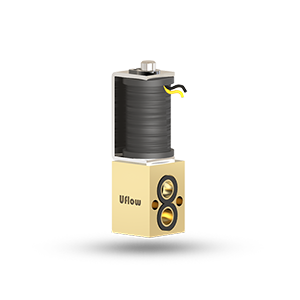
Solenoid Valve
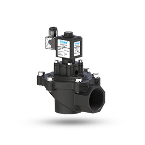
- PCN Series Solenoid Valve
- MCN Series Solenoid Valve
- JAN Series Solenoid Valve
- HCP Series Solenoid Valve
- UGS Series Solenoid Valve
- PBN Series Solenoid Valve
- DAS Series Solenoid Valve
- DAC Series Solenoid Valve
- DAR Series Solenoid Valve
- MNN Series Solenoid Valve
- PBU Series Solenoid Valve
- Auto Drain Valve
- DAA Series Solenoid Valve
-
Pneumatic Valves
-
DCC Series Pneumatic Valves
- 3/2 Single Solenoid Valve With Spring Return (NC/NO) - DCC Series
- 3/2 Double Solenoid Valve - DCC Series
- 5/2 Single Solenoid Valve With Spring Return - DCC Series
- 5/2 Double Solenoid Valve - DCC Series
- 5/3 Double Solenoid Valve With Spring Center - DCC Series
- 3/2 , 5/2 Single Solenoid Namur Valve With Spring Return - DCC Series
- 3/2 Hand Lever Valve Manual and Spring Return - DCC Series
- 5/2 Hand Lever Valve Manual and Spring Return - DCC Series
- 5/3 Hand Lever Valve Manual Return - DCC Series
- 5/3 Hand Lever Valve Spring Return - DCC Series
- 3/2 Single External Pilot Operated Valve With Spring Return (NC / NO) - DCC Series
- 3/2 Double External Pilot Operated Valve - DCC Series
- 5/2 Double External Pilot Operated Valve - DCC Series
- 5/3 Double External Pilot Operated Valve With Spring Center - DCC Series
- 3/2 Push Pull Valve Manual and Spring Return - DCC Series
- 5/2 Push Pull Valve Manual and Spring Return - DCC Series
- 3/2 , 5/2 Double Solenoid Namur Valve - DCC Series
-
DCS Series Pneumatic Valves
- 3/2 Single Solenoid Valve With Spring Return (NC/NO) - DCS Series
- 3/2 Double Solenoid Valve - DCS Series
- 5/2 Single Solenoid Valve With Spring Return - DCS Series
- 5/2 Double Solenoid Valve - DCS Series
- 5/3 Double Solenoid Valve With Spring Center - DCS Series
- 3/2 , 5/2 Single Solenoid Namur Valve With Spring Return - DCS Series
- 3/2 Hand Lever Valve Manual and Spring Return - DCS Series
- 5/2 Hand Lever Valve Manual and Spring Return - DCS Series
- 5/3 Hand Lever Valve Manual Return - DCS Series
- 5/3 Hand Lever Valve Spring Return - DCS Series
- 3/2 Single External Pilot Operated Valve With Spring Return (NC / NO) - DCS Series
- 3/2 Double External Pilot Operated Valve - DCS Series
- 5/2 Double External Pilot Operated Valve - DCS Series
- 5/3 Double External Pilot Operated Valve With Spring Center - DCS Series
- 3/2 Push Pull Valve Manual and Spring Return - DCS Series
- 5/2 Push Pull Valve Manual and Spring Return - DCS Series
- 3/2 , 5/2 Double Solenoid Namur Valve - DCS Series
- SH Series Pneumatic Valves
- Manifolds For Directional Control Valve
-
DCC Series Pneumatic Valves
- Angle Seat Valves
- Pneumatic Actuator
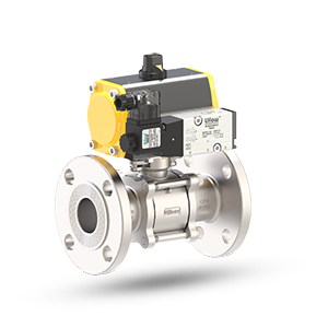
- Ball Valve
- Butterfly Valve
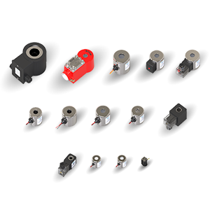
- Solenoid Coil
- Solenoid Proportional Flow Control Valve
- Limit Switch
- Roto Seal Coupling
-
Poppet Valve
-
DCP Series Poppet Valve
- 3/2 Single Solenoid Poppet Valve (NC / NO) - DCP Series
- 5/2 Single Solenoid Directional Control Poppet Valve (Monostable) - DCP Series
- 3/2 X 5/2 Convertible Single Solenoid Directional Control Namur Poppet Valve (Monostable) - DCP Series
- 5/2 Double Solenoid Directional Control Poppet Valve (Bistable) - DCP Series
- 3/2 Single Solenoid Directional Control Poppet Valve (NC / NO) - DCP Series
- 3/2 Single Solenoid Namur Poppet Valve (NC) - DCP Series
- 3/2 Single Solenoid Namur Poppet Valve (NC) - DCP Series
- 3 Way Direct Acting Poppet Type Valve - DCP Series
- 3 Way Direct Acting Poppet Type Valve (Universal)
- 3/2 Single And Dual Pressure Blow Solenoid Poppet Valve (Normally Close) - DCP Series
- DCI Series Poppet Valve
-
DCP Series Poppet Valve
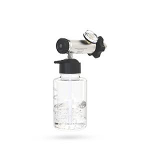
- Medical Oxygen Equipments
-
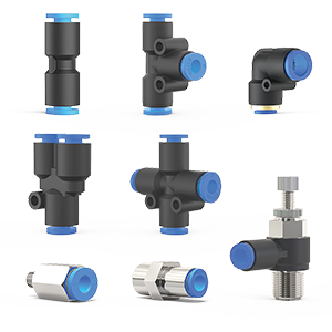
One Touch Fittings
-
VO Series One Touch Fittings
- Straight Union - VO Series
- Different Dia. Straight Union - VO Series
- Union Elbow Reducer - VO Series
- Union Elbow - VO Series
- Union Tee - VO Series
- Union Tee Reducer - VO Series
- Union 'Y’ - VO Series
- Union 'Y' Reducer - VO Series
- Cross Union - VO Series
- Male Connector - VO Series
- Female Connector - VO Series
- Plug - VO Series
- Bulk Head Union - VO Series
- Bulk Head Female Connector - VO Series
- Male Elbow - VO Series
- Female Elbow - VO Series
- Male Branch Tee - VO Series
- Female Branch Tee - VO Series
- Female Run Tee - VO Series
- Male Run Tee - VO Series
- Male Branch Y - VO Series
- Male Connector (Internal Hexagon Socket) - VO Series
- Single Swivel (Internal Hexagon Socket) - VO Series
- Single Swivel (Slotted Head) - VO Series
- Single Swivel (Hexagon Head) - VO Series
- Double Swivel - VO Series
- Triple Swivel - VO Series
- Multi Distributor Union - VO Series
- Multi Distributor Male - VO Series
- VF Series One Touch Fittings
-
VO Series One Touch Fittings
- Plastic Tubing
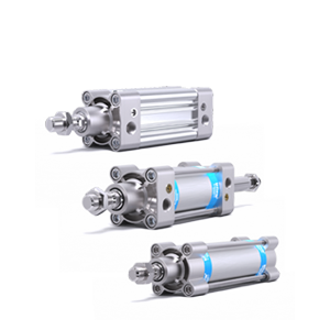
- Air Cylinder
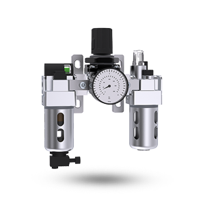
- Air Preparation Unit
- Irrigation
- High Pressure Regulator
- 3/2 Way Direct Acting Universal Valve
-
Silencers / Pressure Gauges
-
Solenoid Valve
- Tech Info
- Certification
- Reach Us
- Career

